Administration

DECT – Traffic Planning and Deployment

Introduction

This page describes how to plan and deploy a site with a DECT system, with respect to radio coverage and traffic capacity.

For most installations, the required radio coverage will determine the required base stations (BS) and the position of the base stations. If the user traffic is high e.g. office environment with help desk, sales and support functions, it may be required to add additional base stations.

Coverage

The choice of base positions is crucial for correct coverage. Identifying the materials present on the site, zone or in the building is essential. The presence of metal surfaces and dense structures will have an impact on coverage. Therefore, it is important to visit the site or to undertake an in-depth drawing analysis with the architect considering the materials used.

Capacity

Capacity calculation is to ensure no calls are blocked due to insuffcient capacity in the installation. Non- homogeneous distribution of the traffic may end up in dividing the site up into several utilization zones.

Audio quality

The audio quality level depends on the service expected by the customer. For example, a company that wants to reach a small number of its employees on the move will put up with a few imperfections, whereas in a “Full DECT” deployment, the quality expected would be equivalent to fixed wired sets.

The actions to carry out to ensure QoS are:

  1. Determine the aims and needs of the customer.
  2. Select the best position for the Base Stations.
  3. Check the traffic capacity.
  4. Identify whether the previous actions need to be adapted according to the QoS expected by the customer.

The following steps should be followed to secure an easy deployment.

  1. Request site information.
  2. Determine the placement of the Base stations to secure coverage.
  3. Check traffic load in the system and if required add more base stations in areas with high DECT traffic density.
  4. After installation, check radio coverage.

Required Information.

The following information shall be available to be able to plan a deployment of a site.

  1. Map of the site: A map of the complete site (if more than one building) and plans of each floor of each building are required. Make sure that dimensions are clearly stated on the maps. Additional information such as the use of buildings (e.g. office, hotel, factory, store, etc.), construction materials (walls, floors, ceilings, etc.), cabling infrastructure, etc. are helpful in estimating positions of the bases in advance.
  2. Number of handsets (HS): Number of handsets, both initial and foreseeable growth. Average traffic density + areas with higher or less traffic.
  3. Allowed and prohibited BS positions: A customer may prohibit installation of bases in certain areas, require the bases to be installed out of sight, etc.
  4. Details of required coverage: It should be clear in advance where coverage is required, e.g. whether elevators, stairwells, toilets, outdoor areas etc. are to be covered as well.
  5. Position of the DECT System and available cabling: Check whether existing cabling can be used for the connection between the DECT System and the bases. (CAT5 or better should be used.) If the type and quality of the available cabling is not enough for the connection to the BSs, new cabling must be installed.
  6. Sensitive electronic equipment: Check whether sensitive electronic equipment is present or not, e.g. laboratory, medical, etc. Although the transmitted power of the bases is very low (EU=250mW, US 120mW) it might interfere with sensitive electronic equipment.
  7. Traffic information: It is necessary to gather information on user density, amount of traffic, whether redundancy is required, etc. This must be clear in advance because it determines the number of bases that are required and therefore also the cabling that is required.

Radio coverage and Speech Quality.

There is always a relation between coverage and speech quality. The further you get away from the BS, the lower the quality. Therefore, it is important to see the relation between the coverage and the expected voice quality.

The following diagram shows the relationship  relation between coverage and voice quality in an indoor environment.

DECT-CoverageQuality.png

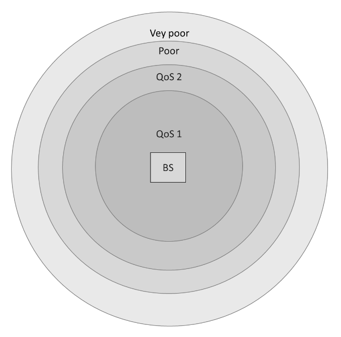
The Quality of Service (QoS) grade of audible voice quality is described below:

  1. (QoS 1) corresponds to a quality with occasionally packet errors but does not affect audible voice quality. (RSSI level higher than -60 dBm).
  2. (QoS 2) corresponds to a quality with packet errors causing occasional minor audible mutes (RSSI level lower than -60 dBm and higher than -70 dBm).
  3. (Poor) corresponds to a quality with clicks, mutes, distorted audio. (RSSI level lower than -70 dBm and higher than -80 dBm).
  4. (Very poor) corresponds to unintelligible audio / no audio at all. (RSSI level lower than -80 dBm.

Which speech quality is required?

The required speech quality depends on the customer requirements and the environment. 

Excellent and Good (QoS 1)

In critical areas like business and office environments, or medical and emergency environments, Excellent and Good voice quality is required (>= -60dBm).

Excellent, Good, Satisfactory (QoS 2)

In less critical areas like basements, factories, warehouses or cold stores, a satisfactory quality may be sufficient (>= -70dBm). In a noisy environment, a click in the voice connection is not noticeable.

Factors affecting speech quality.

The following factors affect the voice quality as well:

Metal Construction

If the construction materials of the building are mainly made of metal, there will be a lot of reflections (fading). In that case the voice quality will be poor (a lot of “clicks” and “mutes”). The effect can be reduced by reducing the distance from the base.

Traffic calculation rules

In most cases, the number of bases required is determined by coverage rather than traffic, however it is a good idea to ensure that there is sufficient capacity when a “Full DECT” solution is deployed.

The calculations must be carried out zone by zone, to determine the optimal density and placement of base stations in a given “zone”. (Reminder: a zone is a space that is homogeneous with regards to coverage level, traffic, and the required quality level). 

The goal is to calculate the maximum number of phone calls/handsets (terminals) you can have in a zone based on the number of base stations available. You can also calculate the maximum number of base stations you can have based on the zone, i.e. maximum density.  

The table below lists the number of channels available in an area/zone.

RegionRF carriersTime SlotTotal no. of Channels
EU1012120
US51260

The channels can be reused, if the base stations are separated by distance, walls and/or floor separation.

User DECT traffic

To calculate the traffic capacity in a DECT system requires knowledge of the users, the traffic load for the users and to understand where the users are in the building. The user traffic load, and their location on the site, shall be used to define the traffic zones in the deployment.

A traffic zone is an area, where the users and the user traffic are homogeneously spread in the Zone.

The traffic load in a traffic zone is the sum of all user generated traffic in the Zone, in the Busy hour, UHBT.

UBHT is the User Busy Hour Traffic (in Erlangs), the hours of call traffic during the busiest hour of the day.

The calculation of the UHBT in a traffic Zone is done per user type:

Tu=∑ ni x ti

ni is the number of users of the same type.
ti is the average traffic per user in the busiest hour of the day expressed in Erlang.

To calculate the total traffic load Tu of all users should be summarized.

Tu-zone= ∑ ni x ti + ∑ nj x tj + ∑ nk x tk

Where ni is the number of users with the traffic load ti and Nr of channels.

The UBHT is for a traffic zone defined as per the User profiles shown below.

  • Low traffic: Normal offices workers, foreman, clerk in stores, warehouse clerks, etc: Use UBHT = 0.1
  • Average traffic: Exec-secretary groups, technique, projects, administration, etc: use UBHT = 0.2
  • High traffic: Helpdesks, Tele-services, sales, buyers, etc.: use UBHT = 0.3
  • Very high traffic Telemarketing, Hot Lines, market rooms, call center: use UBHT 0.7

DECT traffic of users in a zone

The calculation is done per user type (same traffic and same DECT terminal).

Traffic capacity calculation

The total load of the terminals is higher than the DECT traffic of the zone users. You must consider the traffic of the visitors. Visitors should be included in the number of users.

The load due to DECT mechanisms, handover and call setup should not be included in the calculation, as there are reserved channels/slots to handle it (Handover).

Number of terminals

This is the number of terminals to be offered to the customer to meet their needs in terms of traffic.

The calculation method is given for any DECT BS. This calculated number can still be increased in the case of a Full DECT installation according to the requirements of the customers.

The number of terminals finally determined for the traffic aspect must be compared with the number of terminals determined by the coverage requirements.

The higher number will be used for the proposal to the customer.

Calculation of Base Station number

The terminal traffic capacity is linked to 2 parameters:

  • the terminal type which sees 10 channels
  • the minimum number of base stations seen by a terminal at any place in the zone

The table below gives the admissible load per base station with a blocking probability of 1%.

No. of visible BS1234
10 narrow band channels5,0 Erlang6,4 Erlang7,0 Erlang7,5 Erlang

NOTE: Engset Calculator, with a Subscriber traffic at 0,1 Erlang

Base station distribution

The general rule is to distribute the base stations over the whole site or zone to put the mobile handset in a context in which it will see several base stations in the different directions.

This is used to guarantee the fact that it will see some base stations better than others.

A strategic adjustment in base station deployment may be required when the demand for call capacity (traffic) is higher than what is needed for basic coverage, additional base stations can be added in specific areas. This allows handsets to access more available channels, supporting more simultaneous calls and ensuring robust performance even if it deviates from a perfectly even base station distribution aimed purely at coverage.

Site Survey Mode

When the handset is in site survey mode, it will report the 5 strongest DECT base stations in vicinity (From left to right).

To place the handset into Site Survey mode:

  1. Start with the handset in IDLE mode
  2. Press the Menu key
  3. Enter *789872*

DECT-Survey-Mode.jpg

Display ItemDescriptionValue
RPNRadio Fixed Part Number 
The ID of the Base Station you are connected to in Hexadecimal (e.g., 04, 1A).
Ensure you are locking to the correct base.
RSSIReceived Signal Strength Indicator 
Signal strength in dBm.

QoS 1: -60 dBm or higher

QoS 2: -70 dBm or higher 

FEFrame Errors.Should be 0 or very close to it. High errors indicate interference.

To exit site survey mode, repeat the code entry process above OR just power cycle the phone.

BS to BS communication

The BS to BS communication is used to synchronize the internal clock in the BSs with each other. This means that a BS must be able to receive a signal from another BS so seamless handover from BS to BS can be achieved.

In the following diagram, you see the radio signal around the BS on the left, this is called the cell. On the right, it shows BS coverage giving good voice and sync quality.

DECT-SyncVoiceQuality.png

A BS cell can be seen theoretically as a circle around the BS. In the diagram you see two circles around the BS: one in which you have sufficient radio signal strength for a good voice quality, and another (wider) circle with sufficient signal strength for synchronization.

There must always be overlap in the cells to make sure that the voice quality between two BS cells remains good. The wider cell limit around the BS will therefore have quite some overlaps with the other cell or cells and will therefore in so cases reach to the BS of the other cell. This means that the BSs of the overlapping
cells receive (weak) radio signals from each other. However, these radio signals are still strong enough for synchronization purposes.

The minimum required signal strength for synchronization is –80 dBm.

The BS to Handset deployment is done with the following deployment engineering rules.

Type of coverageMinimum RSSI level between a handset and a base
QoS 1-60 dBm
QoS 2-70 dBm

An additional margin of 10 dB should be considered (- 50 dBm and – 60 dBm) in the case of a “Full DECT” QoS level 1 quality requirement.

For BS deployment, each BS must be able to receive a signal from another BS. Compliance with the “BS to HS” engineering rules given above is much more stringent than the “BS to BS” synchronization rules.

Notes:

The synchronization cell limit determines the synchronization cell size. It is highly recommended to execute a Site Survey to determine the cell size for synchronization besides the cell size for voice.

The example given in the diagram above is a worst-case scenario. In practice, a BS will see more than one other BS with sufficient signal strength. Out of these “visible” BSs, it selects the BS that has the shortest synchronization path to the DECT Primary.

Impact of WLAN

The DECT network may be disrupted by a WLAN. This disruption will be a function of the WLAN emission level and the type of antenna used by the 2 networks (Omnidirectional or directional antennas).

To avoid interaction between networks, you must comply with the distances between the DECT BS and the WIFI antennas.

For WLANs, there are several levels of emitted power which, for the sake of simplicity, are divided into 2 sub-groups:

  1. NTP_WLAN network >10 dBm
  2. NTP_WLAN network ≤10 dBm

The minimum distances to be respected with the DECT BSs are as follows:

  1. NTP_WLAN network >10 dBm: – Minimum distance = 2.5M
  2. NTP_WLAN network ≤10 dBm: – Minimum distance = 1M

Specifications by Country

Depending on the country where the DECT system is deployed, there are several limitations that need to be considered.

The table below gives an overview on the different regional specifications in terms of power, number of available channels and best-case range.

CountryPower in dBmNo. of available channelsBest case range Indoor-Outdoor (Meters)
EU241050 – 300
US21540 – 250
Canada21540 – 250
South America241050 – 300
Taiwan24750 – 300
Malaysia20635 – 175
Thailand24350 – 300
Brazil24450 – 300
Japan22645 – 275
Chile221045 – 275
Australia221045 – 275


Contents