MGC loadware is contained on the MGCs compact flash.
The following marking is present on MGC circuit board for daughterboard placement.
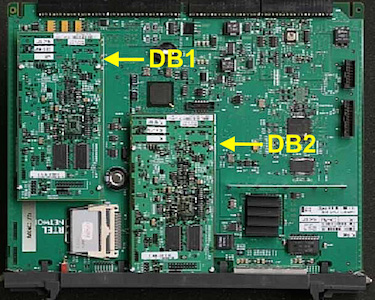
DSP daughterboard slot 1: D/B 1 SLOT 11 LOW OR HIGH DENSITY
DSP daughterboard slot 2: D/B 2 SLOT 0 LOW DENSITY ONLY
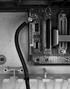
The serial cable connector can be found on the bottom left front of the Meridian Option 11C Cabinet (10 card, NTAK11)>. The NTBK48AA - DB9F to 3/DB25M - 3 Port SDI Cable for the Option 11 is required and plugs into the connector labelled SDI.
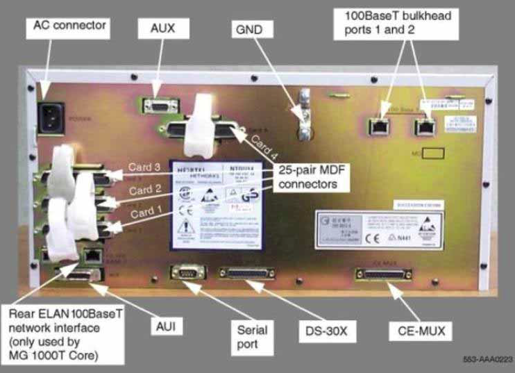
The serial cable connector can be found on the back of the MG 1000E Chassis (4 card, NTDU14). The NTBK48AA - DB9F to 3/DB25M - 3 Port SDI Cable for the Option 11 is required.
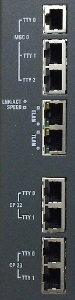
The serial cable connectors can be found on the front of the MG 1010 Chassis (10 card, NTC310). The NTC325AAE6 serial cable kit is required. It contains a N0211606 RJ45 to DB25 (male) adapter which is intended to connect the MG1010 to a DCE device and two RJ45 to DB9 (female) N0211605 adapters which have an integrated null modem and are intended to connect the MG1010 to DTE devices.
MGXPEC offers the option of converting a TDM based CS1000M system to CS1000E, an IP soft-switch solution.
MGXPEC transforms a single IPE shelf into 2 IPMG shelves and allows reuse of existing peripheral equipment.
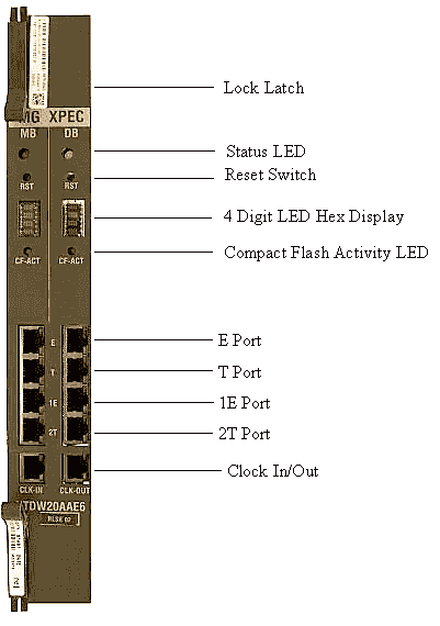
The MGXPEC card has to be seated in the Cont slot in the center of the shelf.
Install new slot label on right side of shelf. The slots on right side are slots 0-7.
The MGXPEC card has two 96-port (NTDW64xx) DSP daughterboards mounted in slot 1 and slot 2 on both motherboard (MB) and daughterboard (DB) cards.
The card slots assigned for DB-96 in DB slot 1 are 11, 12, 13.
The card slots assigned for DB-96 in DB slot 2 are 8, 9, 10.
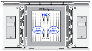
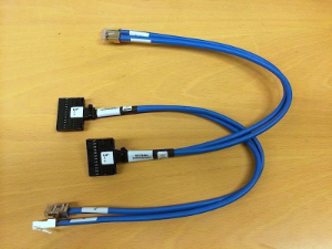
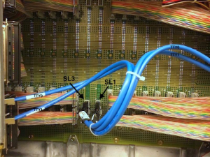
On the back of IPE shelf, NTDW26ABE6 cables are to be connected between the rear SL1 and SL3 connectors, and RJ-45 couplers.
These connections provide TTY0 and TTY1 for each half of MGXPEC. From the back of shelf, the right side is shelf 0 (SL1) and the left side is shelf 1 (SL3).
*pictures shown above are from pbxbook.com website.